
Introduction: The High Cost of Late Manufacturing Changes
Late design changes in the development cycle of medical devices can have a significant regulatory and financial impact on the project. When an engineering team finishes design verification, there may still be tooling or assembly issues that will require change orders, additional testing, and consequently, delayed regulatory submissions. Correcting a manufacturing flaw that was not identified early enough in the design cycle can be up to a hundred times more expensive than fixing it at the 3D computer-aided design (CAD) modeling stage.
Designing medical devices for manufacturability at the right stage of the development cycle can prevent any failures at the submission stage. Although Syrma Johari Medtech’s dedicated Electronic Medical Device DFM Whitepaper discusses the nuances of designing electro-mechanical and printed circuit board assemblies, this guide provides a more general overview of the topic. In this article, we will discuss when to start considering design for manufacturing (DFM) and what design engineers should review during the technical design reviews to ensure that the design can be readily transferred to production.
What Is DFM and When to Introduce It
Design for Manufacturability (DFM) refers to the process of designing components and assemblies in such a way that they can be consistently and reliably produced within the confines of process capabilities. Introducing DFM at the point of design freeze creates an artificial constraint on the design process. For medical device design and manufacturing, the DFM controls have to dovetail directly into the design control process defined by and the United States Food and Drug Administration (FDA) Quality Management System Regulation (QMSR).
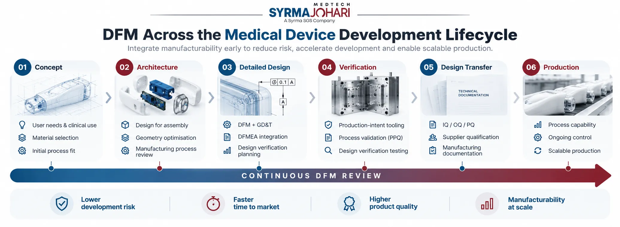
Phase 1: Concept and Architecture (Pre-DHF / Gate 1)
- Screen basic processes and candidate materials for manufacturability at the concept level.
- Assess raw material availability and target sterilization methods for clinical compatibility.
- Look for opportunities to consolidate multiple parts during Design for Assembly (DFA) for cleanroom manufacturing.
- Addressing architectural concerns and geometries at this gate keeps designers from having to retrofit an entire structure just to get it into the DHF.
Phase 2: Detailed Design and Verification (Gate 2)
- Perform part-specific DFM tasks as working drawings and 3D solid models are developed.
- Do injection mold flow analysis to balance wall thickness and draft.
- Apply tolerancing principles ( GD&T) to mechanical features.
- Kick off the Process Failure Mode and Effects Analysis (PFMEA) to track manufacturing-related concerns in parallel with the Design FMEA.
Tooling Progression and Formal Design Transfer
The road to commercialization calls for progressing through well-defined tooling stages while maintaining traceability to the design controls process.
Phase 3: Verification and Production-Intent Tooling (Gate 3)
- Run production intent tooling prior to conducting formal Design Verification (DV) tests
- Use production-grade tooling versus soft aluminum prototype tools for DV testing
- Molds made from aluminum cool at a different rate than molds made from hardened steel, affecting polymer strength and residual stress
- Design verification testing should reflect the actual performance of the production parts
Phase 4: Design Transfer and Scalable Ramp (Gate 4)
- Move from design verification to manufacturing validation by converting design outputs into approved work instructions and device master records
- Establish process capability and statistical process control using multi-cavity tooling.
- Qualify the final process by doing Installation Qualification (IQ), Operational Qualification (OQ), and Performance Qualification (PQ) on the production lines.
- Wrap up design transfer activities by qualifying the production line for commercial ramp.
What Engineers Review: Tooling Physics and Injection Molding
When applying design for manufacturability medical devices (DFM), engineers analyze tooling physics, tolerance distribution, and cleanroom joining methods.
Tooling Physics in Injection Molding
- The wall thickness of a part should be uniform to prevent localized overstressing of materials
- Uneven regions will cool at different rates, causing warping, voids, and sink marks
- Structural ribs should have a thickness equal to half the surrounding wall thickness.
- Draft angles should be added to all sides to facilitate removal after solidification.
- All internal corners should be radiused to prevent stress concentration on the walls.
Micro-Molding DFM Considerations
- Chasing flow fronts in micro-molding requires incorporating open flow channels
- Injection speed should be limited to avoid polymer molecule shearing
- Mold vents should be added to allow trapped air to escape during molding without subjecting the material to oxidative thermal degradation
What Engineers Review: Tolerancing and Cleanroom Assembly
DFM considerations regarding tolerancing and cleanroom joining involve statistical analysis of allowable deviation ranges for tight-fitting parts and studying how these parts will be joined in cleanrooms.
Functional Tolerancing and Statistical Stack Ups
- Tight tolerances should not be specified for dimensions that do not require them, as this creates excessive scrap and rework.
- Geometric Dimensioning and Tolerancing (GD&T) should specify tolerances for all mating surfaces and datum features.
- Root Sum of Squares (RSS) should be used to calculate stack ups instead of worst-case scenarios.
- Tolerances should be analyzed to ensure that they can actually be achieved in production without causing scrap or requiring process adjustments.
Cleanroom Assemblies and Joining Considerations
- Screws and mechanical fasteners should be replaced with snap or press fits to reduce particulate contamination risks.
- Ultrasonic welding should be equipped with internal flash traps to capture excess material from the weld zone to prevent contamination.
- Through-Transmission Laser Welding (TTLW) should be utilized in applications that require hermetic micro-sealing and cannot tolerate particulate contamination, such as in the case of electronics and microfluidics.
- Mistake-proof (poka-yoke) features should be engineered to prevent incorrect assembly, such as by using non-symmetric pin and slot arrangements.
What Engineers Consider: Materials and Sterilization Compatibility
The choice of materials should be guided by considerations of both mechanical performance and biological compatibility.
Biocompatibility and Processing Properties
- Ensure that any resins that will touch patients or carry fluids have been tested for basic biocompatibility according to ISO 10993 standards.
- Select resins likely to retain strength and dimensional stability after heating and humidifying.
- Confirm that each new lot of raw material has consistent flow properties that won’t cause molding issues.
Sterilization Considerations
- Make large-volume parts using an open geometry that allows EtO gas to penetrate and escape during sterilization.
- Avoid any resins that absorb harmful chemical residues after EtO exposure that exceed ISO 10993-7 limits.
- Prevent gamma sterilization damage by screening out materials that become brittle or yellowed, such as POM (Delrin) or unstabilized polypropylene.
- Use high-performance resins like PEEK for surgical instruments likely to be autoclaved multiple times.
Comparing Core Manufacturing Processes
The table below contrasts standard medical device fabrication methods against their primary design rules, physics constraints, and regulatory considerations:
| Manufacturing process | Target applications | Critical dfm geometric constraints | Process physics & failure modes | Regulatory & operational impact |
| Precision injection molding | External enclosures, fluid manifolds, luer fittings | Uniform wall thickness; adequate draft; generous corner radii. | Uneven cooling causes warping, sink marks, and weak weld lines. | Tool rework requires steel modification and restarts dimensional validation. |
| Polymer micro-molding | Vascular clips, intraocular implants, micro-gears | Extremely thin walls; high aspect ratios; precision gates. | High injection pressure degrades polymer chains; premature freezing causes incomplete fills. | Degraded molecular weight shifts in-body absorption, causing safety non-conformances. |
| Swiss cnc turning | Bone screws, dental fixtures, trocar pins | High length-to-diameter ratios; generous thread reliefs; clean tool exits. | Thermal expansion in guide bushings; micro-burrs at thread roots. | Loose burrs in blood-contact zones cause chronic inflammation and trigger recalls. |
| Metal additive manufacturing | Porous spinal implants, custom surgical guides | Feature resolution limits; escape paths for unmelted metal powder. | Directional strength differences; internal voids; rough surface finishes. | Trapped residual metal powder violates patient cleanliness and safety limits. |
Downstream Impact: Aligning Risk Files and the DMR
Medical Device Design for Manufacturability (DFM) directly impacts the device’s regulatory compliance and long-term viability.
Design Traceability Architecture
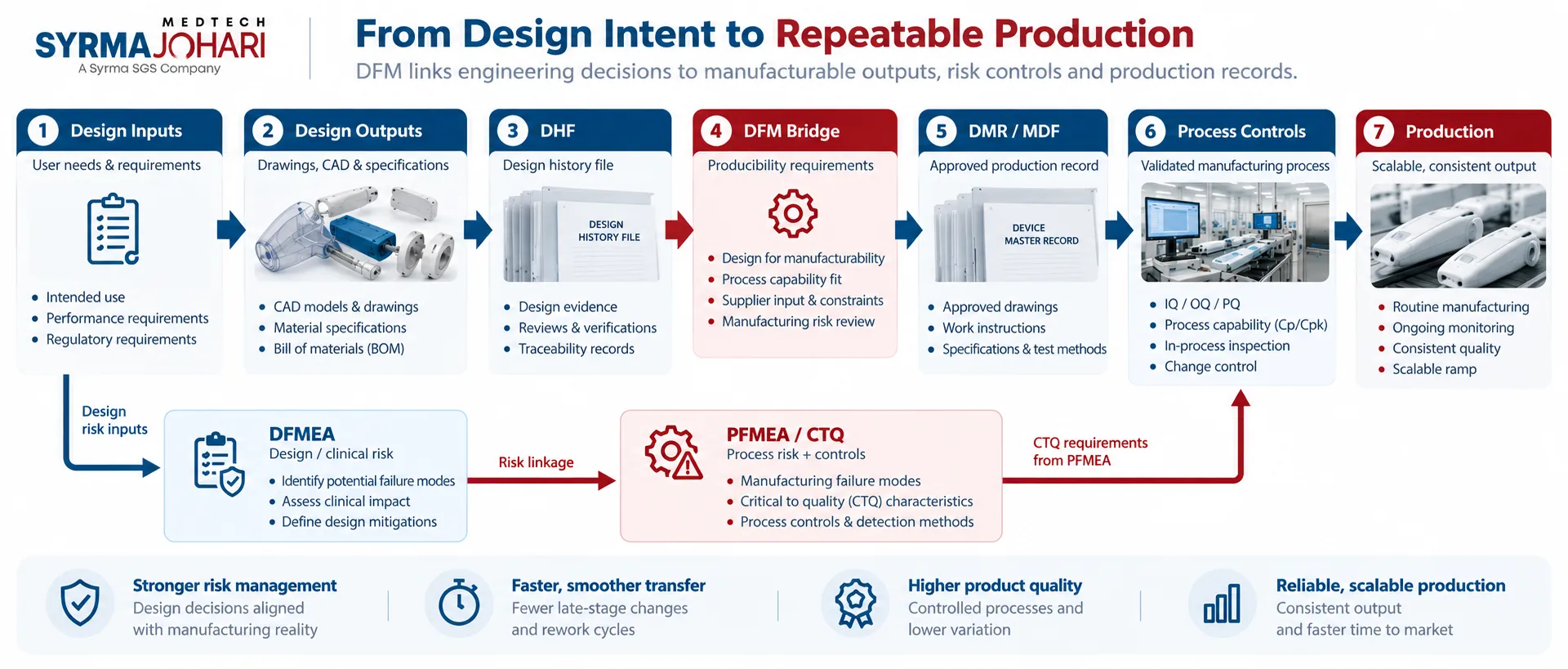
- Design History File (DHF): Captures design inputs and outputs, verification activities, design review gate records, and design failure mode initial models.
- DFM Bridge: Links validated design concepts to achievable manufacturing outputs, establishing producibility requirements.
- Device Master Record (DMR)/Medical Device File (MDF): Describes master production drawings, components specifications, manufacturing work instructions, and quality inspection plans.
- Risk Alignment: Connects DFMEA clinical risk findings to manufacturing process controls in the PFMEA.
Harmonizing DHF and DMR Files
- Move verified engineering files from the DHF to the DMR
- Use production-ready drawings with dimension and material specifications that have been qualified during verification
- DFM exposes misalignment between design and production records that will trigger audit non-conformances
- DFM delivers achievable specifications that the production process can reproduce consistently
Downstream Impact: Connecting Design and Process Risk
- ISO 14971 risk management standards mandate that manufacturing process controls must reduce clinical risk from device failures
- Integrating DFMEA and PFMEA
- Link the DFMEA to the PFMEA
- Identify clinical risk drivers associated with part failure modes (e.g., improper welds causing fluid leakage from a pump)
- Specify Critical to Quality (CTQ) tooling and dimensional specifications to avoid mechanical failures
- Install automated measurements and visual inspections on the production line to detect off-spec conditions
Process Validation Readiness
- Establish process windows for heat sealing, ultrasonic welding, and adhesive curing
- Test process capabilities using production representative equipment during design transfer
- Define control limits to keep process variables within acceptable ranges
- Avoid out-of-specification production when moving to full-rate manufacturing
- Capture manufacturing process challenges early to simplify installation, operational, and performance qualification.
90-Day DFM Implementation Framework
Design for Manufacturing (DFM) for medical devices is a systematic process applied during product development to standardize the interaction between development engineers, toolers, and manufacturers.
Weeks 1-2
- Review the 3D model ensuring that wall thickness is within the permissible range, there are no undercut areas, and the total number of parts is minimized.
- Ensure that the chosen resin is compatible with the intended application according to ISO 10993.
- Conduct a polymer evaluation to ensure that it is compatible with the proposed sterilization method (Ethylene Oxide, Radiation, Autoclave).
- Determine the critical dimensions that define the functional and clinical attributes of the device.
Weeks 3-4
- Use the mold filling simulation to analyze potential molding flaws and knit lines.
- Analyze the impact of the gate location on the occurrence of sinks and warpage.
- Determine molding features that can be eliminated to reduce the overall part complexity.
- Establish a DFM register to document all relevant considerations and concerns.
- Engage with suppliers to establish the availability of raw materials and unique fabrication technologies for the selected materials.
The Second and Third Phase Turns Architecture into Actionable Tooling
Weeks 5-8
- Define dimensions and tolerances using feature-based parameters for all final production prints using GD&T.
- Perform an assembly analysis to define constraints and clearance fit requirements.
- Define final tool cavity geometry, cooling lines, gate locations, and Swiss lathe cut paths.
- Apply process FMEA to finalize inspection criteria and control plans for the manufacturing process.
- The Final Stage Focuses on Pilot Lots and Documentation Freeze
Weeks 9-12
- Construct hardened steel cavity molds and clean-room assembly fixtures.
- Establish inspection criteria using video-based, optical, and mechanical inspection fixtures.
- Conduct a Gage R&R qualification of the fixtures and equipment.
- Perform a pilot assembly run to verify and qualify the process capability for the critical to process dimensions.
- Freeze drawings, component specifications, and standard work instructions in the DMR.
Manufacturing Infrastructure: Syrma Johari Medtech
Taking a medical device from conceptual prototype models into high-volume production requires an experienced partner. Syrma Johari Medtech partners with medical OEMs to industrialize medical device design concepts.
With production facilities located in ISO 13485, and FDA certified cleanrooms, we understand the challenges involved in transitioning from R&D design modeling and into commercial production ramp. Our design engineering staff works with you to understand the nuances of your medical device CAD files, as we identify and resolve complex challenges associated with part geometry and injection molding physics, 5-axis machining routings and automated packaging system assembly.
By combining our mechanical and electronics manufacturing expertise, Syrma Johari Medtech controls the entire design transfer process from risk documentation and production tooling qualification, through to process validation and regulatory compliant Device Master Records. If you are designing complex electro-mechanical medical devices, visit our Electronic Medical Device DFM Whitepaper page where we discuss medical device printed circuit board assembly, surface-mount technology and box build considerations.
Frequently Asked Questions:
What is DFM in medical device development?
Design for Manufacturability (DFM) is the practice of designing parts and assemblies in such a way that they can be consistently and economically produced. DFM seeks to create designs that are compatible with the tools and processes used in production while also meeting clinical requirements and regulations.
When should DFM be introduced in medical device development?
DFM should be introduced in Phase 1 (Concept and Feasibility) prior to locking down the product architecture and design files for production. The process of introducing DFM after verification testing has been completed can lead to the product design having to be re-worked, additional bench testing, updated risk files and regulatory submissions.
How does DFM affect medical device design transfer?
Under ISO 13485 and FDA regulations, design transfer involves demonstrating that design outputs are suitable for manufacturing prior to being released to production. DFM provides the objective evidence needed to make that determination.
Why is tolerance stack-up analysis critical in medical DFM?
When parts are put together, the variations in each part add up. In medical device assemblies, the cumulative effect of part variation can lead to leakage, non-uniformity of latching force, or binding. DFM uses tolerance stack analysis and statistical process control to define how parts can fit together without inducing additional variations, or requiring unnecessary tightening of tolerances during manufacturing.
What is the difference between DFM and DFA?
DFM and DFA are two different but complementary disciplines. DFM focuses on optimizing the fabrication of individual parts and sub-assemblies by minimizing tool wear and optimizing processes such as injection molding, Swiss machining, or additive manufacturing. DFA is about organizing the product architecture to maximize the ease and efficiency of assembly while minimizing the risk of errors and the generation of particulates.
Strategic Commercial Implications
Designing medical devices without regard to manufacturability is a recipe for project delays and budget overruns. When critical engineering decisions are made without consideration of materials degradation, machine tool dynamics or process limitations, the transition from design prototype to commercial manufacturing can be both time consuming and expensive. The iterative process of tooling recuts, re-test and regulatory resubmissions can be extremely costly.
Medical device design for manufacturability transforms the production ramp up process from an exercise in guesswork to an engineered process. Maintaining design intent while also taking advantage of commercial production capabilities enables manufacturers to ensure product performance while also making sure that design files and manufacturing files are in sync prior to the start of production. By engaging in the DFM process early and often, medical device manufacturers can ensure product quality, regulatory compliance and on-time delivery.
Regulatory Disclaimer
The contents of this article are for informational and engineering purposes only and do not constitute legal, regulatory or quality advice. Please consult with appropriate notified bodies, regulatory affairs specialists or governmental agencies on the application of this information to any particular medical device or process.